Week 1:
Week 2:
In this lab, the first draft of the Design Proposal was due. This was reviewed with our technical advisor, Dr. Noh, and suggestions were made about how to proceed with the design process. At first, the goal was to obtain a specimen of the Elephant Hawk Moth and make a casting of its eye, to obtain the exact structure. The moths are not found locally and are not on wing until late June, which is too late for this approach to the project. We then looked into buying a taxonomy specimen, but that also seemed not plausible. An alternative approach was determined; a negative mold for the surface would be created in Creo Parametric, and scaled up 1000 times, to the micron scale, because the machines available could not handle anything at the nanoscale accurately. The negative mold would then be printed on the Rapid Prototyping Machine in Dr. Noh's Laboratory, as his machine has higher resolution capabilities. From there, the actual material would be cast from this negative mold. It was decided it would be more practical to create a thin, flexible film that could be applied or laminated to any material rather than creating a solid material that would need to replace current electronic screen materials, namely PET plastics.
Week 3:
In this lab, We did research on current anti-reflective technologies, we found that main type of technology, used was one that used multiple materials featuring different refraction indices, resulting in multiple refraction light waves. These waves could then be manipulated by the materials chosen so that the waves would cancel each other, reducing glare. We also started figuring out the sizing for the mold dimensions to figure out how tall, wide, far apart, and what angle the protrusions would be made at. We did research based on the actual structure of the moth's eye, which has conical protrusions 400 nm tall and in a hexagonal pattern with 300 nm center to center. We also decided in this lab meeting that we would make various molds with different spacing to test which was the most effective.
Week 4:
In this lab we finalized the dimensions of the molds we would make; the protrusions on each model would be 400 microns tall and 200 microns in diameter. The base of each model would be 1200 microns tall, and would feature a ledge that would be 400 microns wide and 400 microns tall. The spacing of the conical protrusions would vary from model to model. The smallest spacing would have 300 micron center to center of the protrusions. The medium model would be 500 microns center to center, and the large model would be 700 microns. A flat model would also be produced to be used as a control. Our idea is that we would create one piece, approx. 4inches by 4inches and have individual sections with the different spacing. We began to research materials to be used for the model. At this point, our budget is not very high, so we looked into silicone and moldable plastics available online and at local stores. We decided to use a material called MoldMax 15T, which is a clear silicone mix, available from Reynolds Advanced Materials, an online store. The cost of this material- a trial size- was $26.63 plus shipping, totaling $40.43. The material was ordered. During this lab section, Dr. Noh expressed his concern about the possibility of air bubbles ruining our deliverable, and suggested that we use a machine located in his lab that we could put our mold into and it would create a vacuum, sucking out the air bubbles produced from the mixing process.
Week 5:
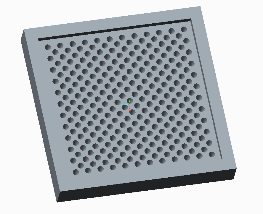
For this lab, CREO models were made for the molds. We changed the design from making one base with multiple sections to making four separate models. Each model will be 1 inch by 1 inch.Significant problems were encountered in creation of the model, so we had to figure out how to make the model without having to extrude each protrusion individually. We figured out how to create a new datum plane to line up our protrusions. We then patterned one protrusion along this datum plane to make one row of protrusions. The datum plane with the line of protrusions was then mirrored, which created all of the protrusions needed for the model. There are images of the molds in the three spacings below. We were told by Dr. Noh that we would receive funding for our project. Due to this, Dr. Noh gave us a list of materials, and a pricing estimate, for these materials that were higher quality and would produce a better deliverable. The materials he suggested and the pricing he gave us were photosilver EnvisionTec, for the Rapid Prototype Machine, and for the model, PDMS: Sylgard 184 kit. The pricing that Dr. Noh provided us with was: $300.00 for the photosilver EnvisionTec and approx. $200.00 for the PDMS: Sylgard 184 kit. Dr. Noh also advised us to list approx. $100.00 for extraneous consumables that we would be using from his lab. Dr. Noh mentioned that he had the photosilver EnvisionTec and the PDMS already in his lab, but we would pay him for using it. He decided that he would estimate the cost as the materials would need to be bought in larger quantities and we would not use that much.
 |
| Small Spacing Between Conical Protrusions (300 microns center to center) |
 |
| Medium Spacing Between Conical Protrusions (500 micron center to center) |
 |
| Large Spacing Between Conical Protrusions (700 microns center to center) |
This week, Dr. Noh expressed his concern about the dimensions of our model. He strongly felt that the base model was not tall enough and the edge was not thick enough or tall enough. When creating the model, we were concerned with creating it too thick and distorting the image quality. When reconsidering, we realized that although it seemed thick to us because we had just scaled it up 1000 times, it was in reality only a fraction of a millimeter. This model was not very feasible because the mold would break or our final product would not be thick enough to withstand the electrostatic forces and transport from the mold to the glass for testing. The sizing of the model was revised: the base is three millimeters thick, the ledge is one millimeter thick and two millimeters wide, and the conical protrusions are the same. The final product will still remain about the same size, just a little bigger than 1 inch by 1 inch, and 3 millimeters thick. The CREO models had to be remade, and will be sent to Kewei to be produced by next week's lab time. Our plan for production is to work in Dr. Noh's lab for the creation of the model. We could mix the silicone, then use an eyedropper to drop the silicone mixture into the mold. Pouring it would be ineffective because of the small scale of this model. The four models could all be cast together, put into the vacuum to evacuate all air bubbles, then set according to the directions on the silicone. This week, we received an email from our financial advisor, Dr. Eli Fromm, with a couple of concerns and things that need to be cleared up before funding.
Week 7:
This week, many concerns were raised by Dr. Eli Fromm about our budget. After reviewing these concerns and alternative pricing options with Dr. Noh, it was decided that our group was not in need of funding by Drexel because all the materials we needed Dr. Noh could provide in his lab. The parts sent to Kewei to be made in the Rapid Prototype machine were .prt files and needed to be .stl files, so that needed changed. Also, when importing the files into the lab computer, Kewei and Abraham found that the dimensions displayed were in millimeters rather than microns. We needed to change our dimensions in our files, then let CREO re-render each piece. Dr. Noh's lab is moving locations starting Friday of week 7. This means that we cannot use his lab facilities to create our prototype. After considering lending us the tools we would need, Dr. Noh decided to set up these tools in an office space in his new lab, and meet us there Tuesday, May 21 at 2:30 pm to create the prototype.
Week 8:
On Monday of week 8, Dr. Noh informed us that the tools were not yet set up in the office space so we would not be meeting on Tuesday. Dr. Noh was not able to attend lab on thrusday, due to the movement of his laboratory. We are at a stand-still because the fabrication needs Dr. Noh's lab, which is out of service. We have been corresponding with Dr. Noh and Abraham, trying to figure out how to get these pieces fabricated as quickly as possible. The movement of Dr. Noh's laboratory and the condition of the rapid prototype machine is out of our control at this point.
Week 9:
The group met with Abraham at Dr. Noh's new laboratory location at 2pm on Wednesday afternoon. The molds for the parts were created on the rapid prototype machine, but the resolution of the machine could not handle the small size of the conical protrusions. The base model is correct though, and it was molded with PDMS. The vacuum desiccator was unavailable for use at this time, so another process was used to remove air bubbles. The Creo models will be modified so that the conical protrusions are larger and will appear on the models. The PDMS is extremely thick, so the conical protrusions need to be increased dramatically in order to accommodate it.
Week 10:
The CREO models were modified to that the conical protrusions were 1 millimeter in diameter instead of .2 and the height is 1.5 millimeters instead of .4, due to these changes the group also had to make the spacing between the conical protrusions larger to allow for the same design. with These changes, the rapid prototype machine was able to construct the molds with very little resolution issues. These molds were then filled with PDMS and put into the vacuum desiccator to remove the air bubbles, then put into the convection oven to set on june 3rd. after waiting a day to ensure the PDMS molds were fully set, the group took the PDMS models out of the plastic molds.

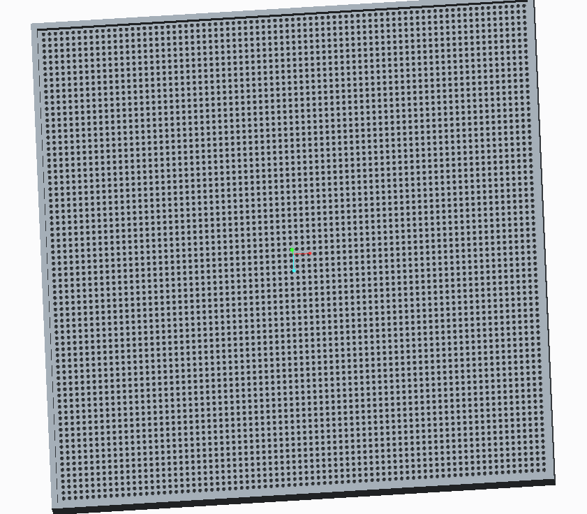
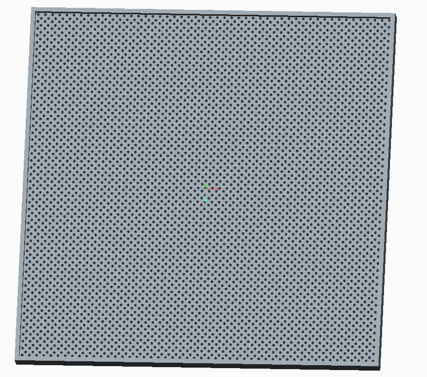
Large Spacing Creo Design and PDMS Model


Medium Spacing PDMS Model and Creo Design


Small Spacing Creo Design and PDMS Model


The small spacing design provided the best absorption of light, as was expected. The problem was, looking at a phone with this model impeded the vision, and thus the use of the device. The following images show how the different spacings appeared on a telephone screen.
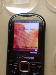


Top Left: Large Spacing Model, Top Right: Medium Spacing Model, Bottom Left: Small Spacing Model, Bottom Right: Control
No comments:
Post a Comment